Monday, April 8, 2013

Recumbent Madness pt. 2: Recumbent's Revenge

Now that I had the frame more or less worked out, it was time to figure out how I was going to steer. Seeing as the front fork is an entire five feet from the forward-most riding position, this presented a bit of a challenge. I thought about just making some stupidly long handlebars, but that seemed pretty cumbersome and wouldn't allow for as tight of a turning radius as I wanted. This next option was to create some kind of remote steering mechanism and place the handlebars directly in front of the rider. The worry I had with that plan was that it would require there to be a bar running directly up between the rider's legs which could cause some serious problems in the event of a sudden stop. 

The third option, and the one I chose to pursue was to place the handlebars under the seat.
Working off the example set by this home-made recumbent bike that sometimes shows up at the college I go to, I started with the idea of using a set of bars to connect the handlebars to the front fork remotely.

These are heim joints. As I understand it, they would have been a perfect solution for this task.
They have a ball shaped thingy with a hole in it inside some kind of collet thing, and you screw them onto whatever you're trying to make move and then put a screw through the hole in the ball thing or whatever, and they hold one thing in place and let another thing move around, I guess.

So, based on my obvious knowledge of how they work, and because buying things is for suckers, I decided to try something that would perform the same function, but that I would make myself. Not exactly knowing where to begin, what I decided I had to do first was to create mounting positions on the front fork for this not-yet-fully-concieved steering system.

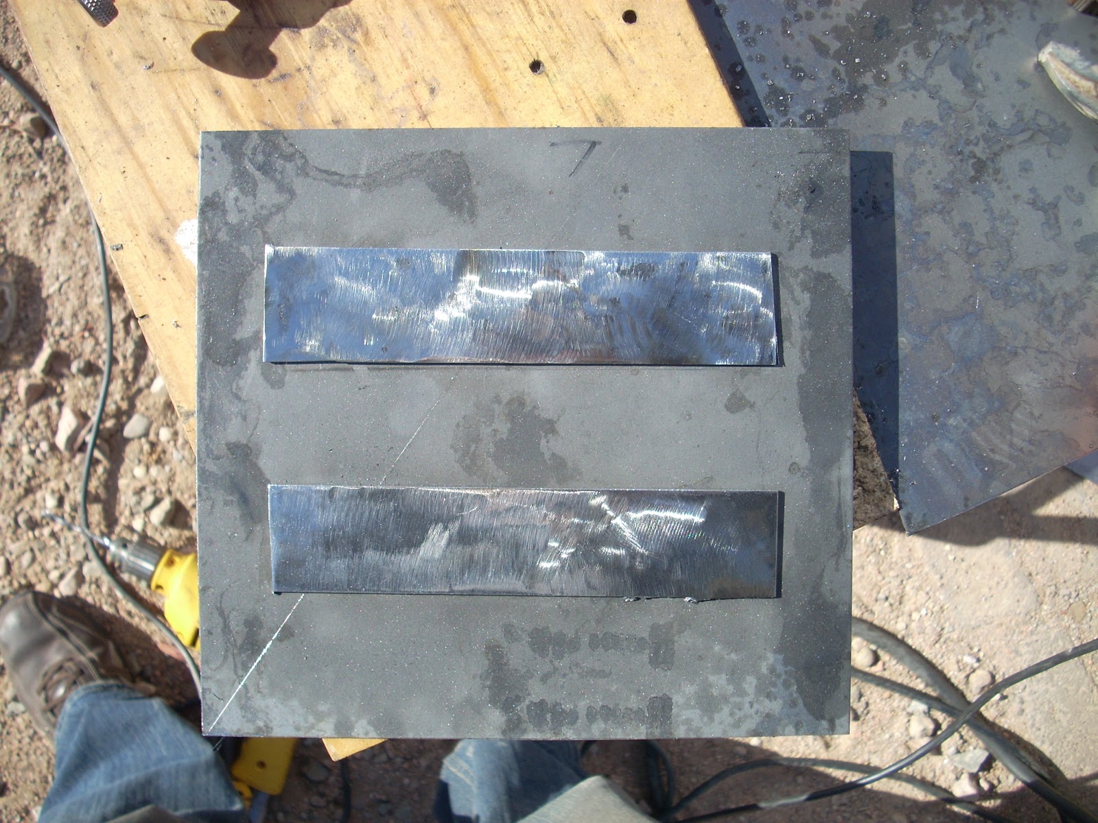
I began by cutting two little pieces of 1/8th inch thickness steel and grinding them into a fat crescent moon kind of shape. I then drilled a hole in both of them of the same diameter as some round bar-stock that I found lying around.
Next, I ground the paint off of a couple places on the bike's front fork and welded the pieces I had just made on as straight and evenly as I could.

The next thing I decided to do was screw up. I was a little overly excited about making the bars that would go between the handlebars and the brackets I had just made, so I started on those. After getting about half-way through making them, I realized that I hadn't even thought to measure how long they had to be. In order to figure this out, I found a small step stool and placed it on the table over the frame so that I could sit on it and put my feet on the pedals to get an idea of how far the handlebars should be from them. 
This revealed to me that the bars I had made were about six inches too short.


After doing that so successfully, I retrieved a pair of BMX handlebars from my pile of bikes. These conveniently had a bracket with screws in it that allowed me to set the handlebars at whatever angle I wanted. I set them to an angle of about 90 degrees.


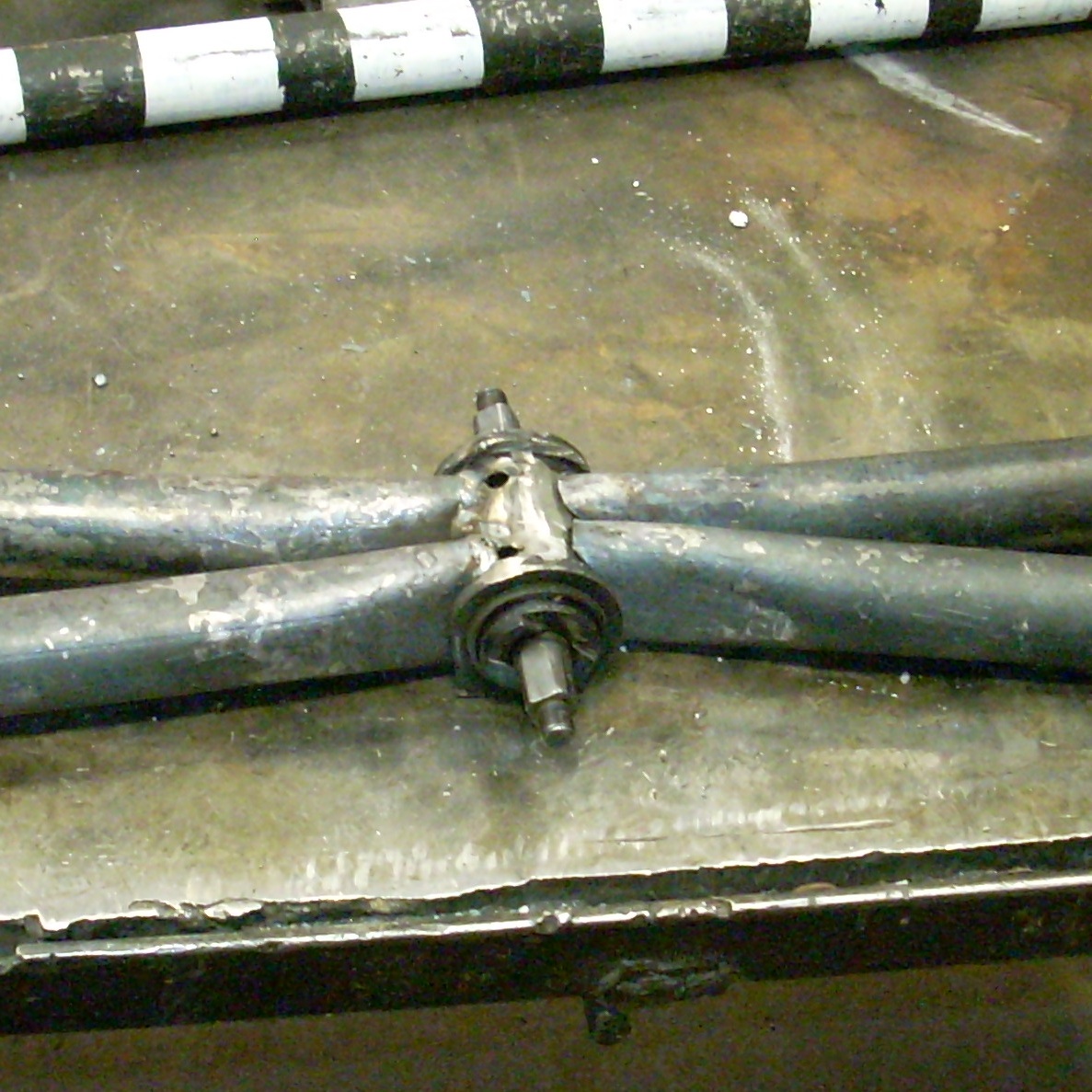
I also retrieved the head tube that I had cut off the little pink bike previously. Using a plasma cutter, I cut a chunk out of each of the two lengths of tubing making up the front half of the bike to create a circular(ish) space.


 I then cut the head tube in half horizontally, and used the bench grinder's wire brush wheel to clean the paint from the halves. Next, I slid one half into the top of the space and one half into the bottom of the space to meet in the middle, then tack-welded them in place.

This is a part I had made earlier on to put the handlebars temporarily onto the upper level of the bike. 

If you remember, there had been a problem with the handlebars coming loose. This part was the culprit. I had made it from a piece of 16 gauge sheet and a left-over wedge nut. Because I did it hastily, the welds were too cold and therefore weak, so I wasn't able to tighten the bolt down adequately for fear of breaking them. Also, the circular piece I had made didn't fit well into the flange of the head-tube.


So I refined the size and shape of of the disk, and re-welded the two pieces together properly. 


Once I was satisfied with that, I found all the parts of the headset assembly required to fix the handlebars to the bike, 
and fixed the handlebars to the bike.

The next thing I had to do was create another mounting bracket to affix to the handlebars. To do this, I used a piece of 16 gauge steel, sheered it into a diamond shape and blunted the lethal looking points with the bench grinder. 
Using the drill press, I then made two holes at the ends of the diamond and two toward the middle of the diamond at the same distance as the two screws on the handlebars closest to the pivot point.

Using the existing screws, I affixed the bracket to the bars.

I then turned my attention to the pieces of round bar I had found. 
Now, I'm not totally sure, but it's possible that I may have stolen them. I did, however, leave my name and number and a very polite note, and thus far no police have shown up at my door, so I may be in the clear. Either way, don't tell anyone.

The bars had apparently been previously used for something, so they were pretty bent and twisted. Using a hammer, anvil and vice, I did the best I could to straighten them out. 


Next I cut them to even lengths that matched the distance from the mounts I had put onto the front of the bike and the vacant holes of the bracket that was screwed onto the handlebars, plus an extra inch. Once I'd done that, I used a vice-grip to hold the two together parallel and clamped the other end down in the vice with 1/2 inch exposed.
Using a rosebud torch tip on an oxy-acetylene set, I heated the exposed 1/2 inch until it was glowing, then beat it to a 90 degree angle with a cross-peen hammer. 

Then I did the same to the other side. 
But because I wasn't paying attention, I did it the wrong way and had to straighten them out and do it again.


Amazingly, after all this, my measurements were right and everything fit correctly on the first try. Each of the 1/2 inch angled bits fit into their respective holes in each of the brackets. Each bar was exactly the right length. Once it was all put together, when the handlebars were turned, so too did the front fork. So, feeling very accomplished, I welded up all my seams, and took a victory nap.

Sunday, March 31, 2013

Archaic Computers and Mechanical Monks

A Chinese text from the 3rd century BCE called the Lie-Zi describes a “figure [that] walked with rapid strides so that anyone would have taken it for a live human being.” Jewish fables portray King Solomon ascending a throne where upon every step an animal figure would reach forward to help him along. There are also stories of a Greek Mathematician from the 4th Century BCE who built a wooden dove that could fly from one perch to another if disturbed. There are many more stories like these throughout history from many other regions. 


It’s hard to know what aspects of these stories are true and which are apocryphal. There is, however, some evidence that objects like these may have existed. For example, in 1900, off the coast of the Greek island of Antikythera an object containing a series of 30 or more complex, interlocking bronze gears was recovered from a shipwreck close to 2,100 years old. Upon analysis, this mechanism was found to be capable of calculating the position of the Sun and Moon as well as the Moon’s phases, solar and lunar eclipse cycles and the motions of planets with the turn of a handle. This raises the idea that these ancient people may have had the technology and the drive to create machines of remarkable complexity, and hints at the plausibility of the fables mentioned above.


An automaton is a complex machine that functions through entirely mechanical means, and which performs tasks with little or no direct human control. Their complexity has varied over time from small wooden contraptions driven by a crank, the wind, or even steam to extremely sophisticated examples of engineering prowess capable of multiple complicated functions. 


Some of the earliest credible accounts of functioning automata come from China and are documented in a set of scrolls called the Shuishi Tujing. This is essentially a list of Chinese inventions compiled in the 6th century by a mechanical engineer named Huang Gun. Described in this account are mechanical wine pourers built onto boats, and a mechanical theater built for the emperor. There was also an interesting chariot built around 2600 BCE. On it was a figure that was connected to the wheels via a set of gears. The gearing would turn the figure to point south no matter the orientation of the chariot.


Examples of these mechanisms became more and more widespread as the Common Era progressed. In 16th century Europe, the Prince of Spain fell down a flight of stairs and was mortally injured. Somehow he managed a miraculous full recovery. In response, the king commissioned Juanelo Turriano, a renowned clockmaker at the time, to create a mechanical likeness of a dead franciscan frier named Diego De Alcala whose ghost he had credited with his son's recovery.


Some of the most complex examples of these automatons date to the late 18th and early 19th century when they became a popular way for clock makers to show off their talents. They were built to do many things including play music and perform magic tricks among others.


This one, for instance, called the Draughtsman-Writer was built by a Swiss mechanist named Henri Maillardet. It was able to perform seven completely separate, exceptionally complicated tasks. It could write three poems and create four drawings all of which resulted from the motion of several slowly rotating cams with a huge number of bumps, notches and valleys cut into them. As they rotated, these cams would transfer motion via a lever-arm to the joints that would create the motion of the automaton's arm. 


The craftsman had to work out how each one of those bumps in the cam would translate into the automaton's movement and create the resultant marks on the paper. Then each one of these moving parts had to be crafted with extreme precision by hand and finally laid out in the proper sequence. This was done long before the invention of computer-aided design and laser cutting, and in most cases even before the advent of factory production. Each cog, gear, cam and mechanism had to be laboriously hand-fabricated using files, hand-saws and other tools of the period.


These artists, engineers, and craftsmen created machines that were able to perform tasks previously confined to the dexterity of the human hand. These mechanisms were built for many reasons. They may have performed a practical function or provided entertainment. They were, in some cases, programmable. Some were even presented as rudimentary imitations of life. In any case, these feats of engineering have not only amazed audiences from history into the modern era; in their time they even spured philosophical discussions about the meaning of life. These machines speak to the uniquely human ability to strain the bounds of our perceived limitations in order to create things that have never been seen before.

Tuesday, March 19, 2013

A Junkyard Jaunt

I had run out of materials. Normally, as a financially-challenged do-it-yourselfer, I would have to choose between spending what little money I had on what was needed to continue my projects or on the solitary Totino's pepperoni and sawdust pizza that would sustain me for the month. Fortunately, Kai and his crew had organized an expedition to Coronado Wrecking and Salvage, and I stowed away.

On our journey we ate exotic foods and saw horrible things. At one point I was discovered and thrown overboard. Luckily we were in Albuquerque, so rather than drowning I walked the rest of the way.

By the time I made it ashore, the rest of the crew had already arrived. We were a total of five souls going by the names Kai, Joe, Frank, Little Frank and myself. 

The vastness of the landscape was overwhelming.


We scaled the great, lime-green cliff of dump truck

to find many useful natural resources.

While the indigenous population was accepting of us and generous with their commodities, some of their customs seemed strange to us. 

Even if we only wanted some, 

we had to take it all or risk inciting their wrath.

With our trade mission done, in the spirit of adventure we carried on.

Some time later, while admiring the incredible scenery,

we got separated in a roadwork graveyard.

Joe went off to pilot a submarine,

then went surfing.

Meanwhile, I got lost in a labyrinth of tanks,

then was crowned King of the Junkyard,

and Kai found some rubber.

Once we regrouped at base-camp we took inventory of our plunder.

Joe had commandeered an enormous length of chain.

For myself, I had annexed 30 leagues of steel tubing and laid claim to a swath of twisty conduit.

Kai, Frank and Little Frank, alas, came away with nothing except the serious case of inspiration they contracted. They should recover with treatment. Nevertheless, a grand and successful adventure was had. 


Thursday, March 14, 2013

Recumbent Madness pt. 1

Various real life things like taxes and an attempt at finding a real job prevented me from posting last week (see "Dear Readers"), and for that I apologize and have written a ludicrously long post to make up for it.

After the successful proof of concept of the top level, it was time to begin constructing the lower, recumbent level of the Pariahcycle. So, I put on some metal, 

and, having never built even a normal bicycle in my life, got to work.


I began by laying it out on the shop floor in order to get a sense of the placement and scale of the parts I would need.
The result is that the upright portion is six feet from hub to hub, and the recumbent portion is ten feet from hub to hub.

I started by cutting the crank-set off of this thing so that the two parts could be used separately.

I was also using more of the horrible plumbing parts that I appear to have an endless supply of.
The ends of the tubing were too large of a diameter to be directly welded to the rear fork.

So I fired up the scary home-made forge that was built by a couple guys named Chris and Aaron. This involved turning on the gas with that red knob in the corner, then getting around to the front as quickly as possible to light it with a propane torch.

With that done, and with considerably less arm hair than I started the day with, I began shrinking the ends of the pipes down to make a better fit.

Then I did the same with the parts that connect to the middle crank, creating a thing that looked like this,


and one that looked like this.

Because of the way that the crank had to be cut off, I was left with this enormous gap.

To remedy this, I found a piece of scrap that was kind of the right shape, but which didn't fit very well.

Fortunately, thanks to some guys called Thomas, Hrayr and Karine, I was able to sort that out with a quickness.

Next, I cut the rear fork off this black BMX,
and began constructing a new back end for it that would connect to the low-profile frame I would have to build.

This was a little complicated.
I cut two pieces of tubing and beveled and shaped the ends so that they would fit snugly against the curved surfaces of the BMX bike. Once I'd done this, I welded them into this triangular shape.

Then I had to create a V-shaped component to match the angle of the parts I had built earlier.
In order to do this, I had to take two pieces of tubing and merge them to the diameter of one piece of tubing so that I could weld them to the triangular structure at an angle for strength.

Because the angle I had to cut out of these pipes was so acute, the chop-saw didn't have a setting for it. As a result, I was forced to cut it out with an angle-grinder.
It turned out pretty sloppy, and required a huge nasty weld that is going to have to be in an unfortunately visible place.


The next thing I had to do was straighten everything out so I could tack weld it all together. I didn't really have a straight-edge that was long enough to be of any use, but that didn't matter because the frame had nothing to use as a reference point anyway. For this reason I resorted to just sighting along it, straightening everything out by eye. Once I thought I had it straight enough I tacked it all together, then stood back and looked at my work.

I had forgotten to double-check it.
It's probably hard to tell from this picture, but it was quite crooked.

I had to cut it apart and try something else.
On my next try, I clamped a long piece of rectangular tubing I had found to it, and tack-welded it again.

There was no really good place to do the clamping however, so it turned out crooked a second time.

I was again forced to cut it apart.
At Kai's suggestion I used string and C-clamps to stretch a line along which I could sight the frame. This worked great (helpful bastard), allowing me to weld it together for the third and final time.

With that, the frame was completed.
All ten feet of it.